
RTOS Systems (Part 1): Multi-Task LED Blinker Without RTOS
7 minute read
Next in Series → Part 2: FreeRTOS LED Control with UART Menu
This series covers RTOS systems development, progressing from bare-metal programming to integrated IoT systems.
- Part 1: Multi-Task LED Blinker Without RTOS (this post)
- Part 2: FreeRTOS LED Control with UART Menu
- Part 3: ESP8266 Wi-Fi Web Server
- Part 4: STM32 + ESP8266 Integrated IoT LED Controller
Project Overview

Short clip: LEDs blinking at different frequencies. SysTick unblocks, PendSV switches.
A minimal, educational bare-metal cooperative scheduler for ARM Cortex-M4 (STM32F407G-DISC1) that blinks multiple LEDs at independent periods using SysTick for timing and PendSV for context switching. This is not an RTOS - it focuses on TCBs, per-task PSP stacks, and a READY/BLOCKED/IDLE state machine.
GitHub Repository: multi-task-led-blinker
Hardware: STM32F407VG Discovery Board (168 MHz ARM Cortex-M4)
Features
- Cooperative scheduling with READY/BLOCKED task states
- Per-task stacks using PSP; exceptions use MSP
- Context switch via PendSV (save R4–R11; restore next task; update PSP)
- SysTick @ 1 kHz as the time base and unblocking engine
- Direct register access (no HAL) to keep mechanics transparent
- Small, well-commented code ideal for learning
How It Works
Per-Task State Machine
Each task transitions between states based on timing:
[READY] ──────────> [BLOCKED]
   ↑    task_delay()     │
   │                     │ SysTick unblock
   │                     ↓
   └─────────────── [READY]

If all tasks blocked ──> [IDLE]
When task ready     ──> [READY]
States:
- READY: Task can run, waiting for scheduler
- BLOCKED: Task delayed by
task_delay(ticks), cannot run - IDLE: All user tasks blocked, CPU in low-power state
Context Switching Path
The scheduler uses SysTick and PendSV for cooperative multitasking:
SysTick (1 kHz)
    │
    ├─> g_tick++ (increment global tick counter)
    │
    ├─> unblock_tasks() (check each task's block_count)
    │
    └─> ICSR.PENDSVSET = 1 (trigger PendSV)
            │
            ↓
    PendSV_Handler
            │
            ├─> Save R4-R11 (current task context)
            ├─> save_psp_value() (store PSP)
            ├─> update_current_task() (select next READY task)
            ├─> get_psp_value() (load next task PSP)
            └─> Restore R4-R11 + set PSP → Resume next task
Key Mechanism:
- SysTick runs at 1 kHz (1ms), unblocks tasks whose delays have expired
- PendSV (lowest priority exception) performs the actual context switch
- Each task has its own stack using PSP (Process Stack Pointer)
- Exception handlers use MSP (Main Stack Pointer)
Timeline Illustration
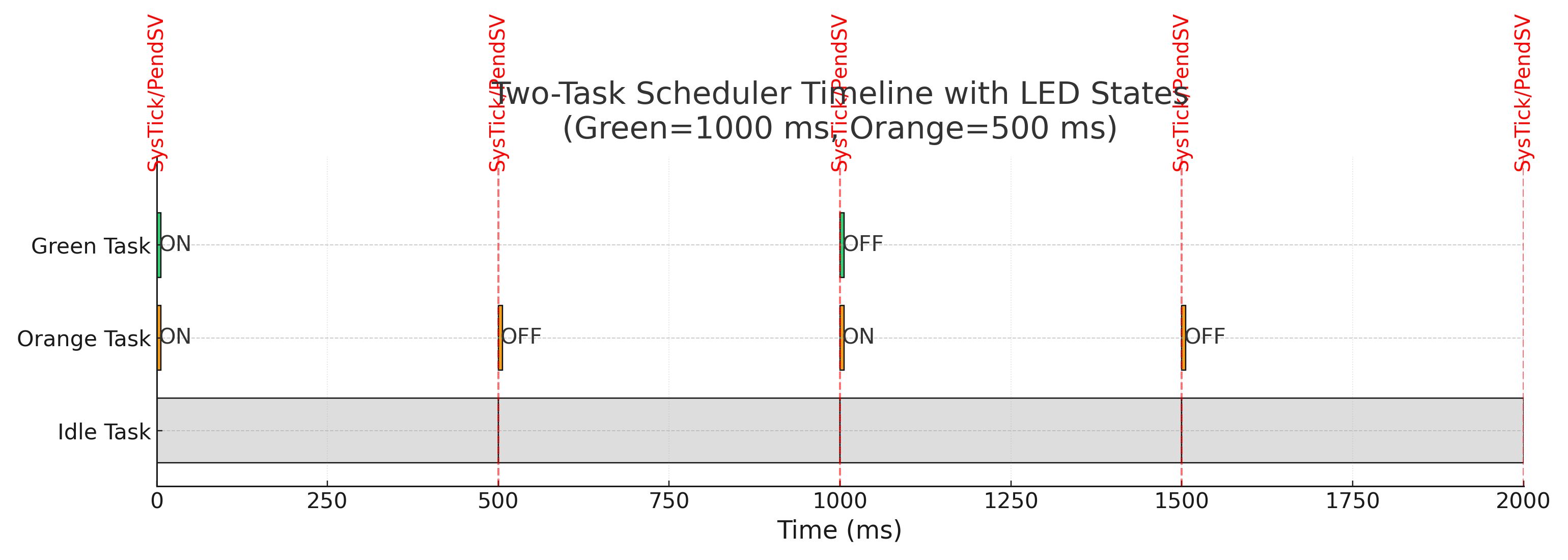
The figure shows Green (1000 ms) and Orange (500 ms) tasks toggling LEDs and blocking, with Idle filling the gaps. Red dashed markers indicate SysTick/PendSV moments.
Task Configuration
Four LED tasks running at different rates:
| LED (GPIOD pin) | Period (ms) | Frequency |
|---|---|---|
| Green (PD12) | 1000 | 1 Hz |
| Orange (PD13) | 500 | 2 Hz |
| Blue (PD15) | 250 | 4 Hz |
| Red (PD14) | 125 | 8 Hz |
Implementation Example:
void task_green_handler(void) {
    while(1) {
        GPIO_ToggleLED(LED_GREEN);
        task_delay(1000);  // Block for 1000ms
    }
}
When task_delay(1000) is called:
- Task sets
block_count = g_tick + 1000 - Task state → BLOCKED
- Scheduler switches to next READY task
- SysTick increments
g_tickevery 1ms - When
g_tick >= block_count, task → READY - Task resumes execution
Build & Flash
Using STM32CubeIDE (Recommended)
- Create new project for STM32F407VGTX
- Import source files from repository
src/directory - Build project (Ctrl+B)
- Flash via ST-LINK (F11 for Debug)
- LEDs start blinking immediately
That’s it! No custom Makefiles or linker script modifications needed.
Project Structure
multi-task-led-blinker/
├── src/
│   ├── main.c      // scheduler + handlers + tasks
│   ├── main.h      // config, memory map, core regs, macros
│   ├── led.c       // minimal GPIO driver (PD12..PD15)
│   └── led.h
├── docs/
│   ├── demo.gif
│   └── timeline.png
└── README.md
Key Concepts
1. Task Control Block (TCB)
Each task has metadata stored in a TCB:
typedef struct {
    uint32_t psp_value;     // Task's stack pointer
    uint32_t block_count;   // Tick count when task unblocks
    uint8_t current_state;  // READY, BLOCKED, or IDLE
    void (*task_handler)(void);  // Function pointer
} TCB_t;
2. Stack Architecture
High Address
┌─────────────────┐
│  Task 1 Stack   │  ← Task 1 PSP
├─────────────────┤
│  Task 2 Stack   │  ← Task 2 PSP
├─────────────────┤
│  Task 3 Stack   │  ← Task 3 PSP
├─────────────────┤
│  Task 4 Stack   │  ← Task 4 PSP
├─────────────────┤
│  Idle Stack     │  ← Idle PSP
├─────────────────┤
│  Scheduler MSP  │  ← Exception/Interrupt stack
└─────────────────┘
Low Address
- Each task has 1 KB private stack
- PSP (Process Stack Pointer) tracks per-task stacks
- MSP (Main Stack Pointer) used for exceptions/interrupts
3. Context Switching
When PendSV fires:
Save context (outgoing task):
PUSH {R4-R11}      // Save general-purpose registers
MRS R0, PSP        // Get current Process Stack Pointer
STMDB R0!, {R4-R11}  // Store R4-R11 to task stack
BL save_psp_value  // Save PSP to TCB
Load context (incoming task):
BL update_current_task  // Select next READY task
BL get_psp_value        // Get next task's PSP
LDMIA R0!, {R4-R11}     // Load R4-R11 from task stack
MSR PSP, R0             // Set PSP to new task
POP {R4-R11}
BX LR                   // Return (resume task)
What I Learned
Bare-Metal Fundamentals
- Clock configuration - Setting up PLL for 168 MHz operation from 8 MHz HSE
- GPIO initialization - Configuring GPIOD pins as outputs (push-pull mode)
- SysTick timer - Configuring 1ms tick for time-base generation
- Exception priorities - PendSV at lowest priority ensures context switch happens safely
ARM Cortex-M Specifics
- Dual stack pointers - MSP for handlers, PSP for tasks
- PendSV handler - Tail-chaining optimization for efficient context switches
- NVIC configuration - Setting up SysTick and PendSV priorities
- Register manipulation - Direct access to CMSIS registers (no abstraction layers)
Scheduler Design
- Cooperative multitasking - Tasks must explicitly yield (no preemption)
- Tick-based delays - Simple time management using global tick counter
- State machine - Clean separation of READY/BLOCKED/IDLE states
- Idle task - Fills CPU time when all tasks blocked
Limitations & Next Steps
Why Not Use This for Real Projects?
This scheduler is intentionally minimal for learning. It lacks:
- ❌ Priority-based scheduling (all tasks equal priority)
- ❌ IPC mechanisms (semaphores, queues, mutexes)
- ❌ Dynamic task creation/deletion
- ❌ Preemption (tasks must cooperate)
- ❌ Timer services
- ❌ Memory management
Next Step: FreeRTOS
In [Part 2], I rebuild this project using FreeRTOS, which provides:
- ✅ Preemptive scheduling with priorities
- ✅ Queues and semaphores
- ✅ Software timers
- ✅ Dynamic task management
- ✅ Robust, battle-tested kernel
This bare-metal exercise provided the foundation to understand what FreeRTOS does under the hood.
Troubleshooting
No LED Activity
- ✅ Check GPIOD clock enable:
RCC->AHB1ENR |= (1 << 3) - ✅ Verify GPIO mode bits set to output (MODER = 01 for each pin)
- ✅ Confirm LED pins PD12–PD15 mapping
PendSV Not Firing
- ✅ Confirm
ICSR.PENDSVSETwrites in SysTick handler - ✅ Ensure PendSV priority is lowest (higher number = lower priority)
- ✅ Verify SysTick running at 1 kHz
FAQ
Is this an RTOS?
No — it’s a tiny, bare-metal cooperative scheduler. To grow toward an RTOS, you’d need:
- Priority queues for tasks
- Preemptive scheduling
- IPC primitives (queues, semaphores, mutexes)
- Software timers
- Dynamic task create/delete
Do I need to clear PENDSV manually?
No — hardware clears the pending state on exception entry. Manual clears can drop legitimate requests.
Why use PendSV instead of SysTick for context switch?
PendSV is lowest priority. If higher-priority interrupts occur (e.g., UART, timers), they run first. The context switch happens only when all interrupts complete, ensuring safe task transitions.
References
- ARM Cortex M4 User Guide
- STM32F407 Reference Manual
- Fast Bit Embedded Brain Academy: Embedded Systems Programming on ARM Cortex-M3/M4 Processor
- Making Embedded Systems by Elecia White
Next in Series → Part 2: FreeRTOS LED Control with UART Menu